- 您现在的位置:买卖IC网 > Sheet目录1214 > EVAL-ADE7758ZEB (Analog Devices Inc)BOARD EVAL FOR AD7758
�� �
�
�PRELIMINARY� TECHNICAL� DATA�
�EVAL-ADE7758EB�
�ANALOG� INPUTS� (P4,� P5,� P6,� P7,� P8� AND� P11)�
�Voltage� and� current� signals� are� connected� at� the� screw�
�terminals� P4-P6� and� P7-P8� and� P11� respectively.� All� analog�
�input� signals� are� filtered� using� the� on-board� anti-alias� filters�
�before� being� presented� to� the� analog� inputs� of� the� ADE7758.�
�The� default� component� values� which� are� shipped� with� the�
�evaluation� board� are� the� recommended� values� to� be� used� with�
�the� ADE7758.� The� user� can� easily� change� these� components,�
�however� this� is� not� recommended� unless� the� user� is� familiar�
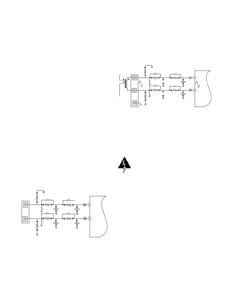
�Using� a� CT� as� the� current� transducer�
�Figure� 2� shows� how� a� CT� can� be� used� as� a� current� transducer�
�in� one� phase� of� a� 3-phase� 4-wire� distribution� system� (Phase�
�A).� In� a� three� phase� distribution� system� Phase� A,� Phase� B� and�
�Phase� C� are� nominally� 120°� phase� difference� to� each� other.�
�Each� phase� usually� requires� a� connection� of� this� type� for�
�current� sensing.�
�with� sigma-delta� converters� and� also� the� criteria� used� for�
�selecting� the� component� values� for� the� analog� input� filters� -�
�See� ADE7758� datasheet.�
�Current� sense� inputs� (P4,� P5� and� P6)�
�P4,� P5� and� P6� are� two-way� connection� blocks� which� allow�
�ADE7758's� current� inputs� of� phase� A,� B� and� C� respectively�
�to� be� connected� to� current� transducers.� Figure� 1� shows� the�
�connector� P4� and� the� filtering� network� which� is� provided� on�
�I� max� =� 40A�
�CT�
�1:1800�
�SH1A�
�8� ?�
�JP2�
�SH1B�
�8� ?�
�JP4�
�100� ?�
�JP25�
�100� ?�
�JP1�
�JP5�
�1k� ?�
�JP6�
�1k� ?�
�TP2�
�33nF�
�TP4�
�33nF�
�ADE7758�
�IAP�
�355mV�
�rms�
�IAN�
�the� evaluation� board.�
�The� resistors� SH1A,� SH2A,� SH1B,� SH2B,� SH1C� and�
�SH2C� are� by� default� not� populated.� They� are� intended� to� be�
�used� as� burden� resistors� when� CTs� are� used� as� the� current�
�transducers—� see� using� a� CT� as� a� the� current� transducer� .�
�The RC networks R9/C5, R7/C8, R15/C9, R13/C12, R21/�
�C13,� R19/C16� are� used� to� provide� phase� compensation� when�
�a� Current� Transformer� is� being� used� as� the� current� transducer�
�with� the� ADE7758—see� using� a� Current� Transformer� as� the�
�current� transducer.� These� RC� networks� are� easily� disabled� by�
�placing� JP4,� JP1,� JP10,� JP7,� JP16� &� JP13� and� removing� C5,�
�C8,� C9,� C12,� C13� and� C16� (socketed).�
�The� RC� networks� R10/C6,� R8/C7,� R16/C10,� R14/C11,�
�R22/C14� and� R20/C15� are� the� anti-alias� filters� which� are�
�required� by� the� on-chip� ADCs.� The� default� corner� frequency�
�for� these� LPFs� (Low� Pass� Filters)� is� selected� as� 4.8kHz� (1k� ?�
�&� 33nF).� These� filters� can� easily� be� adjusted� by� replacing� the�
�components� on� the� evaluation� board.� However� before� adjust-�
�ing� the� component� values� the� user� should� first� review� the�
�ADE7758� datasheet.�
�ADE7758�
�Full� Scale�
�differential� input� =� 0.5V�
�Figure� 2� —� CT� connection� to� Current� Channel�
�The� CT� secondary� current� is� converted� to� a� voltage� by� using�
�a� burden� resistance� across� the� secondary� winding� outputs.�
�Care� should� be� taken� when� using� a� CT� as� the� current�
�transducer.� If� the� secondary� is� left� open,� i.e.,� no� burden� is�
�connected,� a� large� voltage� could� be� present� at� the� secondary�
�outputs.� This� can� cause� an� electrical� shock� hazard� and�
�potentially� damage� electronic� components.�
�Warning!�
�Using� a� CT� without� a� burden� resistor�
�can� lead� to� electrical� shock.�
�The� anti-alias� filters� should� be� enabled� by� opening� jumpers�
�JP5,� JP6,� JP11,� JP12,� JP17� and� JP18—see� Figure� 2.�
�Most� CTs� will� have� an� associated� phase� shift� of� between� 0.1°�
�and� 1°� at� 50Hz/60Hz.� This� phase� shift� or� phase� error� can� lead�
�P4� 1�
�P4� 2�
�SH1A�
�R11�
�JP2�
�SH1B�
�R6�
�JP4�
�R9�
�100� ?�
�JP1�
�R7�
�100� ?�
�JP3�
�C5�
�33nF�
�C8�
�33nF�
�JP5�
�R10�
�1k� ?�
�JP6�
�R8�
�1k� ?�
�TP2�
�C6�
�33nF�
�TP4�
�C7�
�33nF�
�IAP�
�IAN�
�to� significant� energy� measurement� errors,� especially� at� low�
�power� factors.� However� this� phase� error� can� be� corrected� by�
�writing� to� the� Phase� Calibration� registers� (APHCAL,�
�BPHCAL� and� CPHCAL)� in� the� ADE7758.� The� software�
�supplied� with� the� ADE7758� evaluation� board� allows� user�
�adjustment� of� the� Phase� Calibration� register.� See� the� Evalu-�
�ation� Software� Description� for� more� information.�
�For� this� example,� notice� that� the� maximum� analog� input�
�range� on� the� Current� channel� is� set� to� 0.5V.�
�When� using� the� ADE7758,� the� Gain� for� Current� channel� has�
�been� set� to� 1.� The� maximum� analog� input� range� and� gain� are�
�Figure� 1� —� Current� Channel� on� the� ADE7758� evaluation�
�board�
�–2–�
�set� via� the� Gain� register� (GAIN)� —� see� the� ADE7758� data�
�sheet� .� The� evaluation� software� allows� the� user� to� configure� the�
�current� channel� gain.� This� means� that� the� maximum� peak�
�differential� signal� on� the� current� channel� is� 0.5V.�
�REV.� PrB� 08/03�
�发布紧急采购,3分钟左右您将得到回复。
相关PDF资料
EVAL-ADE7759EBZ
BOARD EVALUATION FOR ADE7759
EVAL-ADE7762EBZ
BOARD EVALUATION FOR ADE7762
EVAL-ADE7763ZEB
BOARD EVALUATION FOR ADE7763
EVAL-ADE7816EBZ
BOARD EVALUATION FOR ADE7816
EVAL-ADE7878EBZ
BOARD EVAL FOR ADE7878
EVAL-ADE7880EBZ
BOARD EVAL FOR ADE7880
EVAL-ADE7953EBZ
BOARD EVAL FOR ADE7953
EVAL-ADF4002EBZ1
BOARD EVAL FOR ADF4002
相关代理商/技术参数
EVAL-ADE7759E
制造商:AD 制造商全称:Analog Devices 功能描述:Active Energy Metering IC with di/dt Sensor Interface
EVAL-ADE7759EB
制造商:Analog Devices 功能描述:Power Metering, Active Energy Metering IC with di/dt Sensor Interface 制造商:Analog Devices 功能描述:EVAL FOR EN METER IC W DI/DT SENS INTRFC - Bulk
EVAL-ADE7759EBZ
功能描述:BOARD EVALUATION FOR ADE7759 RoHS:是 类别:编程器,开发系统 >> 评估演示板和套件 系列:- 标准包装:1 系列:- 主要目的:电信,线路接口单元(LIU) 嵌入式:- 已用 IC / 零件:IDT82V2081 主要属性:T1/J1/E1 LIU 次要属性:- 已供物品:板,电源,线缆,CD 其它名称:82EBV2081
EVAL-ADE7762EBZ
功能描述:BOARD EVALUATION FOR ADE7762 RoHS:是 类别:编程器,开发系统 >> 评估演示板和套件 系列:- 标准包装:1 系列:- 主要目的:电信,线路接口单元(LIU) 嵌入式:- 已用 IC / 零件:IDT82V2081 主要属性:T1/J1/E1 LIU 次要属性:- 已供物品:板,电源,线缆,CD 其它名称:82EBV2081
EVAL-ADE7763EB
制造商:Analog Devices 功能描述:EVALUATION BOARD DOCUMENTATION ADE7763 ENERGY METERING IC
EVAL-ADE7763ZEB
功能描述:BOARD EVALUATION FOR ADE7763 RoHS:是 类别:编程器,开发系统 >> 评估演示板和套件 系列:- 标准包装:1 系列:PSoC® 主要目的:电源管理,热管理 嵌入式:- 已用 IC / 零件:- 主要属性:- 次要属性:- 已供物品:板,CD,电源
EVAL-ADE7816EBZ
功能描述:BOARD EVALUATION FOR ADE7816 RoHS:是 类别:编程器,开发系统 >> 评估演示板和套件 系列:- 标准包装:1 系列:PSoC® 主要目的:电源管理,热管理 嵌入式:- 已用 IC / 零件:- 主要属性:- 次要属性:- 已供物品:板,CD,电源
EVAL-ADE7854EBZ
制造商:Analog Devices 功能描述:EVALUATION BOARDS - Boxed Product (Development Kits)